

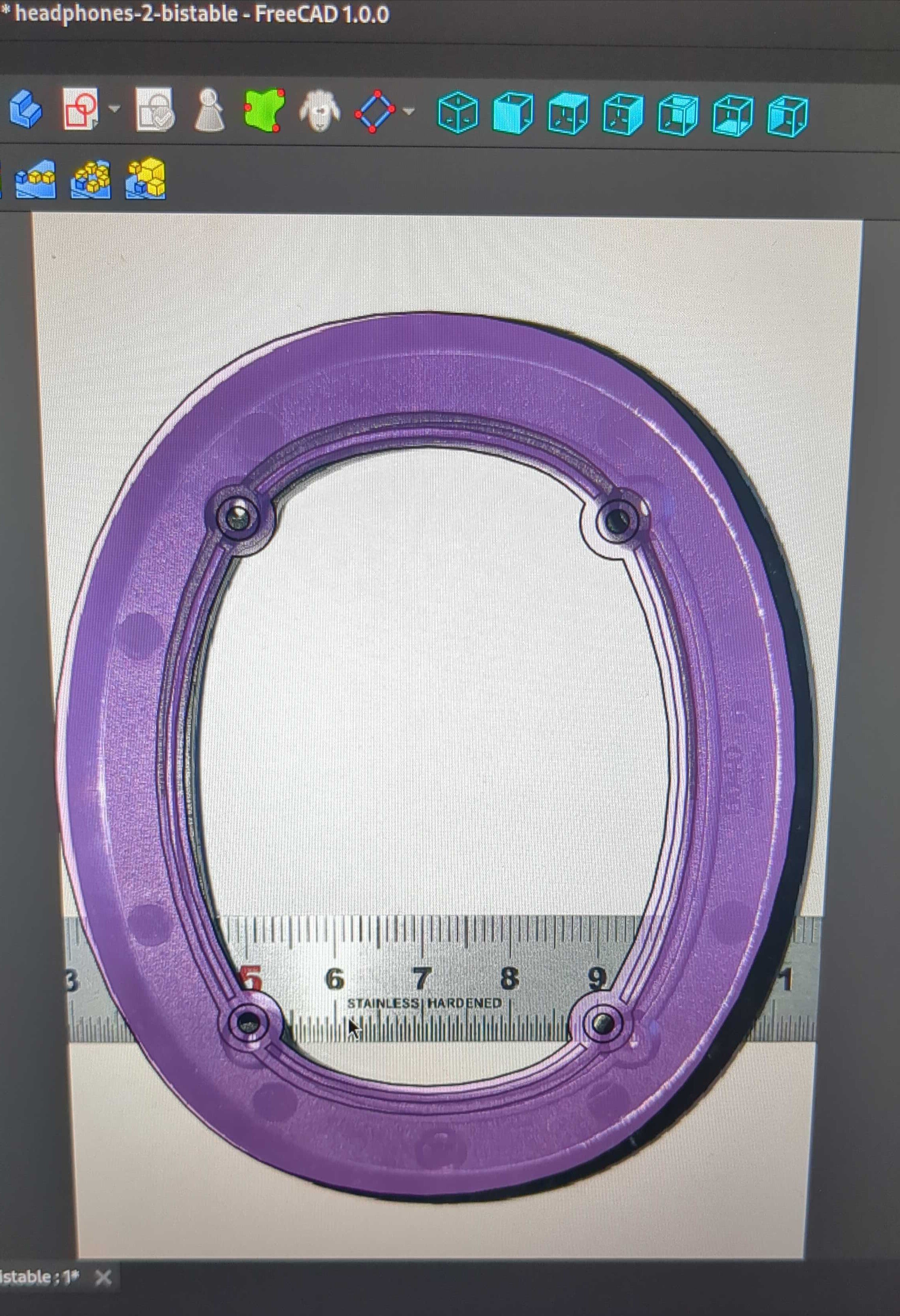
I’ve managed to do reverse engineering of circuit boards using GIMP and rough alignment of layers using images like the one pictured. I want to use images to reverse engineer parts in CAD, but the minor lens distortion of a camera on a phone at ~20cm high on top of a stack of objects to keep it eyeballed flat is not enough. The result is off in multiple planes. There are minor errors in my curves in the transparent CAD part pictured, but the hole pattern is correct. The picture has been calibrated to 20mm against the ruler. Any suggestions on how to make this usable for replicating the ellipse that crosses the holes ±0.05mm?
Do you have a flatbed scanner? Like a photocopier printer?
Literally put the item on the glass of the flatbed and hit scan, stick an etched mm ruler beside it facing the scanner if you want scale.
It’s generally the most effective way by far to perform this.
I’ve used it to copy the perfect profile of an extruded aluminium ebike battery housing, to print a replacement cap after the first got cracked.
Basically when you try to use your phone to perform a task like this, you’ll need to account for the inherent lens distortion of your camera, which is a pain in the ass
A decent laser etched steel carpenter’s square should run you $10-15 and give you 2 dimensions!
As others have said, using a flat bed scanner will save some work. If you need to photograph it though:
-
Use paper with grid lines as background (not sure the name, used to use it in maths at school). This will give you not just an index for scale but also for ‘squareness’.
-
Position camera perpendicular to subject
-
Use a telephoto or zoom lens from a distance rather than wide angle from close up to minimise lens distortion.
-
Import image into GIMP or photoshop and use rulers, guides and transform tools to scale the image correctly and make it perfectly square.
-
Matching the colour perfectly is more complicated and I won’t go into that here.
Let me know if you need any more tips. I photograph a lot of artwork and documents.
Graph paper is the squares paper, I believe :)
-
I see 2 problems. Both can be solved.
Position of the camera sensor plane parallel to your object’s plane.
Place a sheet of squared paper on the table for the test shot. So you can see the proper alignment in both dimensions at once. Use a tripod to fix your camera above the table.
Tell the camera to insert a little time delay (3-5 seconds) when shooting to eliminate the motion from your finger’s push.
(Edit: if you really want to stay very cheap, you could try without the tripod. But use the squared paper behind your object. Then do it all in the post processing).
Lens distortion.
Use a lens of a well known brand.(I don’t know if it is possible with a phone instead of a real camera). Then use the software “darktable” for post processing, because it has a library of lenses and can properly correct the distortion with 1 click.
If you can rig the camera so it will stay at a fixed distance from the subject, you can stitch together as many exposures as you need and it will minimize the distortion. Keep a grid in the background to help with stitching. The Google Photoscan app does something like that.
Flatbed scanner, as someone else said, would be best.
For a camera take the photo with the highest focal length you can (biggest zoom lens on your phone). Fill the frame as little as possible (distortion gets worse as you get closer to the edges). Both GIMP and Photoshop have filters to remove lens distortion. It would help to put two straight edges, (one horizontal, one vertical) near the edges of the photo. When you remove the lens distortion properly these lines will become straight.
You could also try photogrammetry to get a rough model to use as a reference.
A scanner would be your best bet.
But you could go wild and ditch the photo idea.
The original piece was modeled in CAD. Simply follow the logical path for how it was originally done.
Measure the outermost dimensions and draw a rectangle as construction geometry. Then play around drawing a couple of circles - chances are that the top and bottom curves are circles and are trimmed and joined with eachother with say blend curve to preserve tangency.
Also measure the distance of the holes to the rest of the geometry. How far are they from the top and sides. You could measure their distance to eachother crosswise too to narrow down the measurement error.
The geometry is built around simple measurements, if you can work out the sketch tools and constraints, you can probably match the original with high precision.
That is what the purple overlay is already. However there are multiple ellipses that are not the same and very minor variation is important. The original part was likely made using surfacing workflow and not a parametric sketch type workflow. The error really needs to be ±0.05 or better, thus the reason it is worth chasing the picture based reverse engineering.
Are you sure the part is as complex as you say? It just looks like lense distortion to me. You can’t get an accurate copy from a simple photo. You need special equipment to capture the true proportions
Try a few transfer methode. Try using carbon or soot and press the object on a paper. Then scan the paper. Build the outer shape on CAD then measure the smaller details and crevasses.
